Put the most charging power behind the vehicles that must leave first.
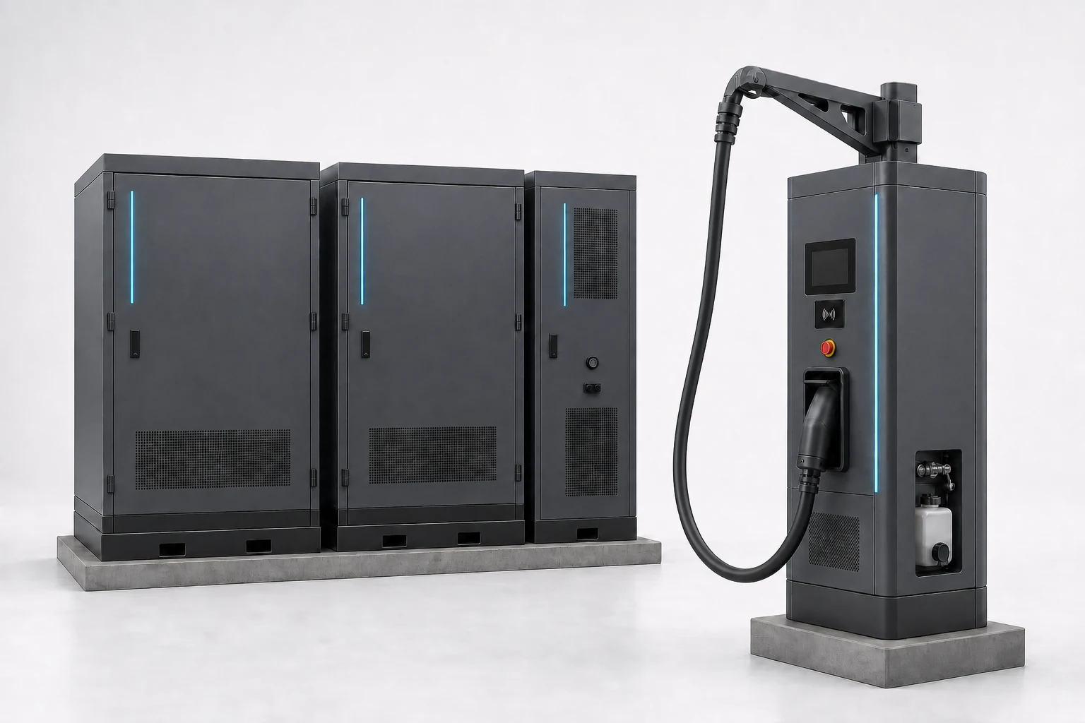
Choose the fleet charging terminal from route energy, depot time, departure priority, vehicle acceptance and available site power. Liquid-cooled configurations serve the vehicles with the tightest turnaround.
Request price and availability
Your selected product is attached automatically. Add only what you already know.
Use the higher-power lane where a missed departure matters.
Separate vehicles by route energy and usable connection window before selecting equipment.
Logistics return-to-base fleet
Group vehicles by arrival, energy deficit and next departure so charging priority follows the operating schedule.
Heavy-truck depot
Screen route energy, usable dwell, vehicle charging capability, pull-through needs and shared site power before fixing the charging lane.
Mixed-speed depot
Keep lower-cost overnight charging for vehicles with time, and reserve the higher-power terminal for tighter windows.
Phased fleet expansion
Define the first operational group and the electrical path for later vehicles before committing the full site at once.
Configure the fleet terminal around the operating window.
Choose the terminal pattern around arrivals, energy need and next departures. We match the hardware and liquid-cooled cable configuration to the fleet schedule.
Departure-priority fleet terminal
View scope details
- Project power
- 180–480 kW per port, matched to vehicle energy need, stop time and depot power
- Operating role
- Higher-power position controlled around named departure groups
- Vehicle connection
- The vehicle inlet, DC interface and liquid-cooled cable arrangement are matched to your project
The vehicle charging curve, energy deficit, available site power and simultaneous schedule determine the final rating and allocation.
Phased high-power depot lane
View scope details
- Project power
- First-stage rating and later power path confirmed from the depot plan
- Operating role
- A defined initial vehicle group with space and electrical planning for expansion
- Vehicle connection
- Fleet connector mix and cable reach confirmed from representative vehicles and bay geometry
The phased project plan separates included first-stage equipment from future civil, electrical and charging capacity.
See where the power cabinets and charging terminals fit in the depot.
Use these views to compare centralized power equipment, vehicle-side terminals, equipment zones and cable routing.
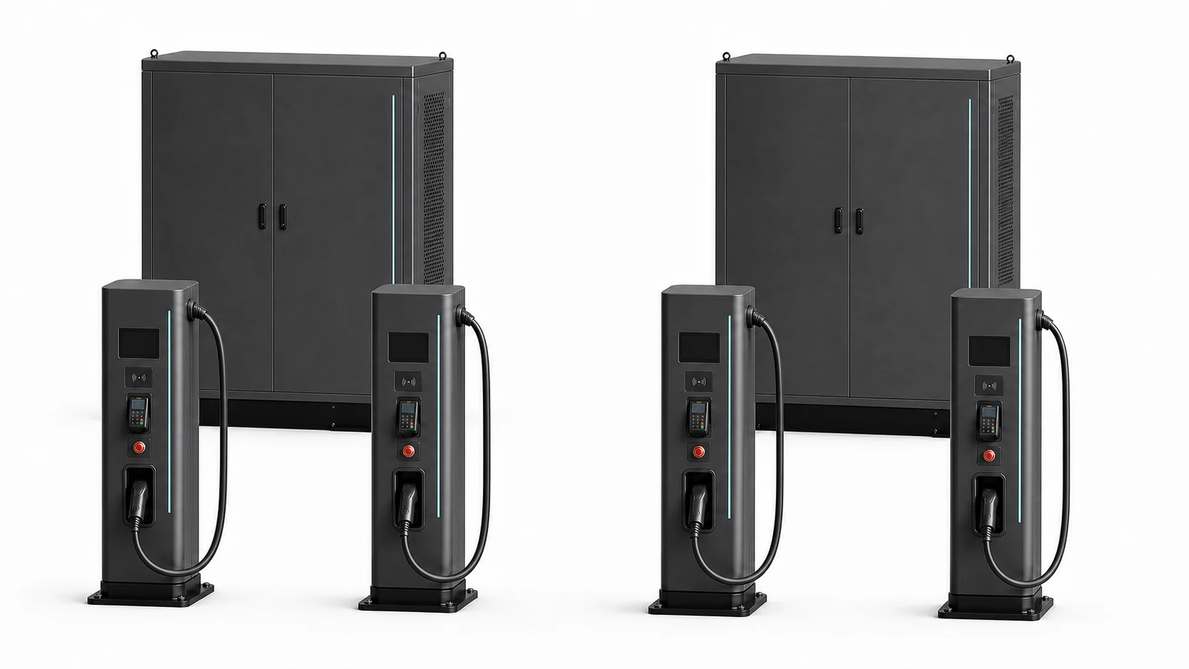
Use this centralized-cabinet and remote-terminal example to discuss equipment zones and cable routing. The final layout follows the bay plan and cable reach.
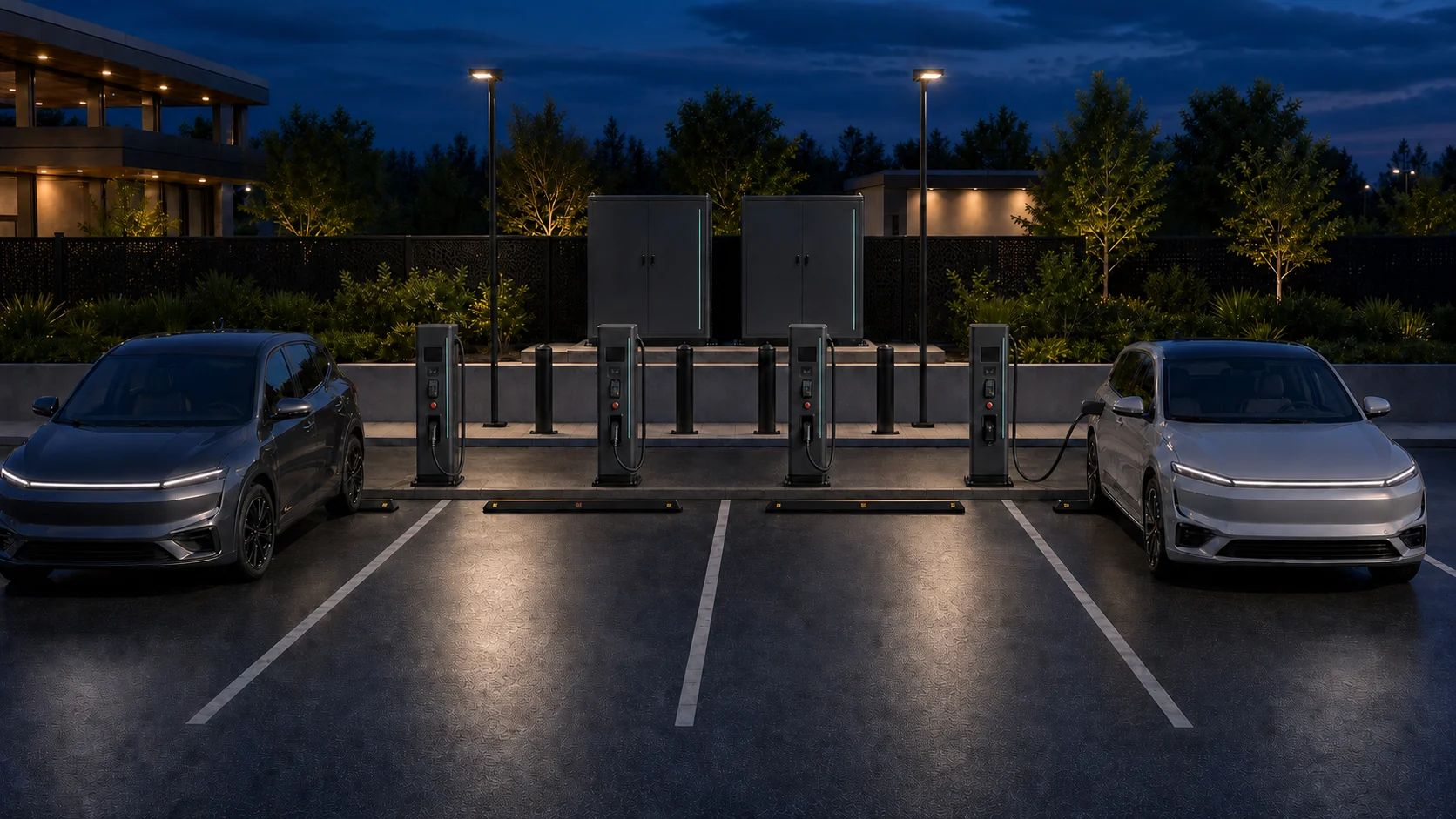
Use this multi-bay depot example to discuss bay reach, equipment separation and departure flow.
These images show possible family layouts. Your proposal lists the cooling system, output, simultaneous capacity, quantity and site layout.
Match the cable to the vehicle and charging need.
High-power fleet planning requires the actual vehicle inlet, supported charging behaviour, battery and route data, cable reach and destination requirements.

CCS1
North America

CCS2
Europe / global
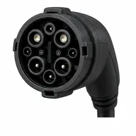
GB/T DC
China
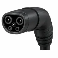
NACS DC
North America
Send typical vehicle specifications and charging data with the route and departure schedule. We will match the connector, liquid-cooled cable arrangement, usable rating and destination documents.
The terminal becomes useful when power follows the fleet schedule.
Connect the higher-power lane to departure-priority power control, fleet operating software and the slower overnight lane.
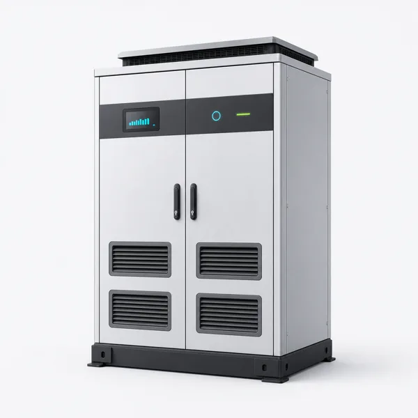
Dynamic load management
Share available depot power by departure time so priority vehicles charge first.
See how it fits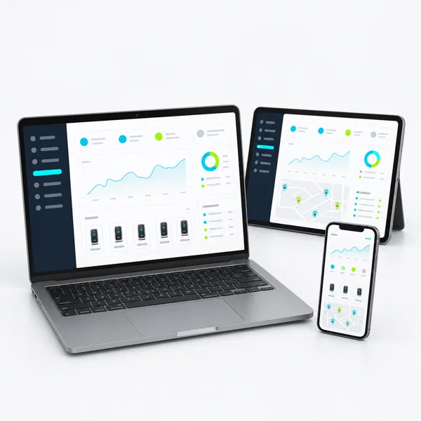
Charging management platform
Configure vehicle, driver, shift, status and reporting workflows included in the project scope.
See how it fits
Commercial AC charging
Serve vehicles with longer connected time on an AC lane and preserve higher power for urgent departures.
See how it fitsMatch route, vehicle and depot data before choosing the terminal.
Use the planned power allocation to check that named vehicle groups can be ready for their departure windows before equipment quantities are fixed.
- Representative vehicle models, inlet type, battery data and supported DC charging behaviour
- Route energy, plug-side energy need, arrival time, next departure and reserve requirement by vehicle group
- Number of simultaneous connections and the rule for departure priority or exception charging
- Verified utility, transformer, switchboard and demand-profile data with the depot power ceiling
- Bay geometry, pull-through or reversing movement, cable reach, overhead or ground routing and impact protection
- Destination documents, testing, commissioning, warranty, spare parts and support responsibilities
Get the right information at each buying step.
Download the worksheet, add your site details and receive a matched configuration with a clear handover path.
Commercial EV charging project worksheet
Share the site, vehicles, power information, destination and timeline needed for a useful first proposal.
PDF - 2 pages Download the worksheetSelected fleet charging system sheet
Lists the cabinet and terminal layout, vehicle interfaces, power allocation, cable system and departure-priority settings included.
Project configuration pack Add this document scope to my quoteFleet system installation and handover pack
The confirmed order controls the applicable equipment layout, interfaces, commissioning, warranty, spare-parts and support documents.
Included with your confirmed order Plan my handover packUse the worksheet to share your starting details and receive one coordinated scope for specifications, documents, responsibilities and commercial terms.
Answers before you select a liquid-cooled fleet charging family.
Does every fleet vehicle need the highest-power terminal?
Start by grouping vehicles by plug-side energy need and connected hours. Vehicles with a longer overnight window can use lower-power charging, while the higher-power lane is reserved for the groups with tighter departures.
How is the fleet terminal rating selected?
Compare route energy, vehicle acceptance, connected time, simultaneous demand and available depot power. Those inputs determine the equipment rating and allocation rule matched to your project.
Why does the vehicle charging curve matter?
A terminal can deliver only what the vehicle accepts under the actual charging conditions. Compare vehicle data with the target energy and time window instead of relying on terminal nameplate power alone.
Can the depot be built in phases?
Yes. Define the first vehicle group, power equipment and operating target, then identify the civil, electrical and space provisions intended for later stages. Each included stage is written into its project documents.
What information should a fleet buyer send?
Send representative vehicle charging data, route energy, arrival and departure schedule, vehicle count, simultaneous connections, depot electrical data, parking layout and the target project date.
Turn the terminal into an operating depot plan.
Put the route-critical charging lane into your depot blueprint.
Choose the fleet scenario, spaces, market and connectors. Your brief will include the starting terminal quantity plus the power-control, software and site data needed for a useful proposal.
Takes about one minute. Receive a matched equipment and service plan for your site.